
Foot Switch
Foot Switch
XF-502S Emergency Stop Safety Foot Switch

The XF-502S Foot Switch is a heavy-duty industrial safety foot switch that combines foot-operated machine control with an integrated emergency stop button. Designed for applications requiring both operational convenience and enhanced emergency protection, the XF-502S features a rugged aluminium alloy housing, protective safety guard, emergency stop function, and IP65 protection rating. Equipped with a high-performance XZ-15GW22-B switch mechanism and dual-contact configuration, it provides reliable control and rapid emergency shutdown capability for industrial machinery, automation systems, and production equipment.

Material: Aluminium Alloy

Inner Switch: XZ-15GW22-B

Rating Load: 15A / 250VAC

Contact Form: 1C + 1C

Protection Degree: IP65

Cable Length: Custom Length Available

Mechanical Life: ≥1,000,000 Operations

Safety Guard: Included

Emergency Stop Button: Included

2e68a3da4c690a02.webp

Product Features
  • Wide Range of Applications
    Wide Range of Applications

    Ideal for machine tools, stamping equipment, welding systems, packaging machinery, assembly lines, industrial automation systems, and equipment requiring emergency stop protection.

  • Long Mechanical Service Life
    Long Mechanical Service Life

    Designed for more than 1 million mechanical operations, ensuring dependable long-term performance.

  • Industrial-Grade Environmental Resistance
    Industrial-Grade Environmental Resistance

    Suitable for environments exposed to dust, moisture, oil mist, vibration, and other industrial contaminants.

  • Custom Cable Length Available
    Custom Cable Length Available

    Cable length can be customized according to installation requirements and equipment layouts.

  • Hands-Free Equipment Control
    Hands-Free Equipment Control

    Allows operators to keep both hands available for material handling and machine operation while maintaining precise equipment control.

  • Enhanced Operational Safety
    Enhanced Operational Safety

    Combines foot control, safety guard protection, and emergency stop functionality in a single compact unit.

  • IP65 Dustproof and Waterproof Protection
    IP65 Dustproof and Waterproof Protection

    Sealed construction protects against dust ingress and water jets, ensuring reliable performance in harsh industrial environments.

  • Reliable 15A Switching Capacity
    Reliable 15A Switching Capacity

    Rated for 15A at 250VAC, suitable for industrial machinery, automation equipment, and motor control systems.

  • Heavy-Duty Aluminium Alloy Housing
    Heavy-Duty Aluminium Alloy Housing

    Constructed from high-strength aluminium alloy for excellent impact resistance, durability, and long service life in industrial environments.

  • Protective Safety Guard Design
    Protective Safety Guard Design

    The enclosed safety cover helps prevent accidental operation while providing convenient foot control.

  • Dual Contact Configuration
    Dual Contact Configuration

    Features a 1C + 1C contact arrangement, enabling separate control and emergency stop circuits for enhanced functionality.

  • Integrated Emergency Stop Function
    Integrated Emergency Stop Function

    Equipped with a prominent emergency stop button that allows operators to immediately stop equipment in emergency situations, improving workplace safety.

Specifications
Product modelXF-502S
Contact resistance25mΩ(initial value)
Insulation resistance100mΩ Above DC500V
Withstand voltage≥2000VAC
Mechanical Life1,000,000ops above
Electrical Life100,000ops above
Operating temperature-20~+70°C
Operating Humidity≤85%
MaterialAluminium
Inner SwitchXV-15GW22-B
Rating Load15A/250VAC
Contact Form1C+1C
0utgoing Cable--
Protection DegreeIP65
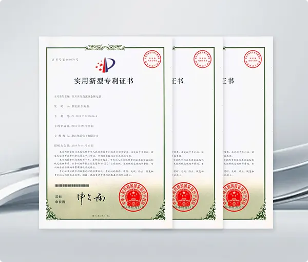
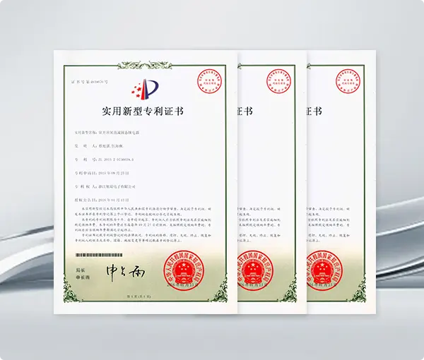
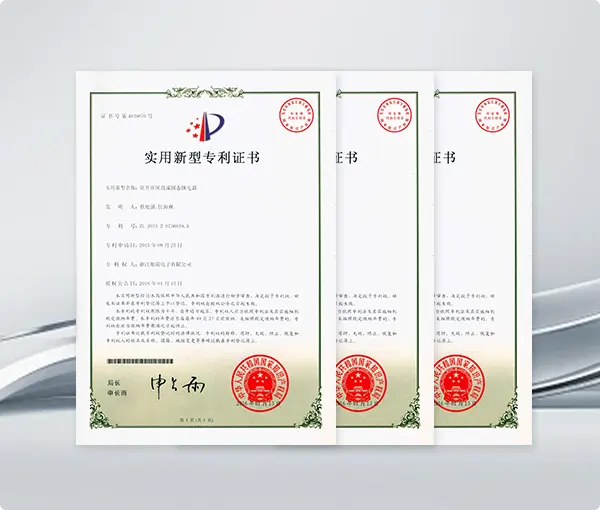
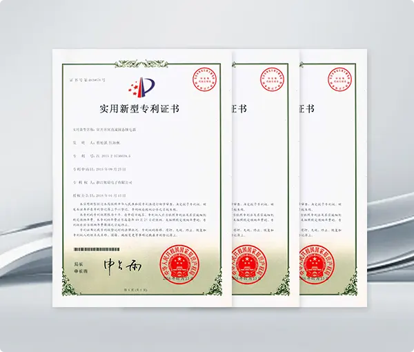
Product Certification
  • 01Certification for the Chinese market

    Compliant with GB national standards, with CCC and CQC certification for domestic sales and bidding compliance.

    Certification for the Chinese market Certification for the Chinese market
  • 02EU Market Certification

    Comply with CE, RoHS, REACH and EN standards, approved by TÜV & VDE, and support ATEX certification for explosive hazardous areas.

    EU Market Certification EU Market Certification EU Market Certification
  • 03North American Market Certification

    UL, CUL and CSA certified, conforming to North American electrical safety specifications for US and Canada market access.

    North American Market Certification
  • 04Japanese, Korean, and Asian markets

    Adapt to Japanese PSE and Korean KC certification, follow JIS and KS local standards to meet market access regulations of Japan and South Korea.

    Japanese, Korean, and Asian markets
Product Introduction & Process
  • 1
    Raw Material Inspection

    Metal or engineering-plastic housings, pedals, shafts, springs, internal switches, cables, terminals, cable glands, anti-slip pads, gaskets, and protective covers are inspected before production.

    2
    Housing and Pedal Forming

    Metal housings and pedals are produced through die casting, stamping, or machining. Plastic components are injection molded. Pedal shape, mounting points, hinge locations, and internal component interfaces are dimensionally inspected.

    3
    Surface Finishing

    Metal components are deburred, polished, cleaned, and treated with powder coating, painting, plating, or another corrosion-resistant finish. Surface adhesion, coating thickness, and appearance are checked.

    4
    Shaft and Hinge Manufacturing

    Shafts, hinge pins, bushings, and mechanical linkages are machined or formed. Their diameter, straightness, surface finish, and fit are controlled to provide smooth pedal movement.

    5
    Internal Switching Module Preparation

    Micro switches, contact blocks, or other internal switching devices are tested before assembly. Contact configuration, operating force, terminal type, and electrical rating are verified.

    6
    Cable Processing

    Cables are cut to the specified length, stripped, crimped, soldered, or fitted with terminals and connectors. Conductor continuity, crimping strength, polarity, and cable appearance are checked.

    7
    Internal Wiring Assembly

    The cable is connected to the switching module according to the required contact configuration. Insulating sleeves, wire guides, grounding components, and strain-relief parts are installed.

    8
    Return Spring and Pedal Mechanism Assembly

    The pedal, return spring, shaft, hinge, actuator, and internal switch are assembled. Spring force and actuator position are adjusted to ensure smooth operation and reliable automatic return.

    9
    Cable Gland and Strain-Relief Installation

    The cable gland, sealing ring, and cable clamp are assembled using controlled torque. Cable movement must not transfer mechanical stress directly to the internal electrical connections.

    10
    Sealing and Housing Closure

    Gaskets and sealing components are installed around the housing, pedal shaft, and cable entry. The upper and lower housings are joined with screws, rivets, or model-specific fastening methods.

    11
    Pedal Operating Test

    Pedal travel, operating force, return force, switching point, release point, anti-slip performance, and mechanical movement are checked. The pedal must operate without sticking or unintended switching.

    12
    Electrical Safety Testing

    Each foot switch is tested for circuit continuity, NO/NC contact function, contact resistance, insulation resistance, dielectric strength, ground continuity where applicable, and correct cable wiring.

    13
    Durability and Protection Testing

    Sample units undergo repeated pedal operation, cable pull, cable bending, impact, load, temperature, and ingress protection testing according to the product specification.

    14
    Final Inspection and Packaging

    Housing appearance, pedal movement, cable length, plug or connector type, terminal configuration, labels, screws, guards, and accessories are inspected before packaging.

Download
  • All
  • Selection Guide
  • Product Manual
  • Outline Drawing
Application Scenarios
Customization & Delivery
We support the following types of customization
  • Electrical Parameter Customization :

    Custom voltage & current, AC/DC type, zero-cross or random trigger.

  • Mounting Structure Customization :

    Custom mounting, terminals and non-standard dimensions.

  • Heat Dissipation & Protection Customization :

    Custom heat dissipation, high isolation, potting and anti-corrosion protection.

  • Function Upgrade Customization :

    Overheat/overcurrent protection, anti-interference, delay and soft start optional.

  • Appearance & Brand Customization

    Custom logo, marking, OEM/ODM and personalized solution design.

  • Proofing Cycle

    Regular customization: 3-7 working days

    Complex Customization: 7-15 working days

    Urgent Sampling: 24-72 hours

  • Proofing Cost ( $ )

    2222 US dollars

  • MOQ

    Conventional products have no minimum order quantity. Customized products can be consulted with customer service

  • Delivery Time

    The delivery time usually varies depending on the quantity and model of the order, usually 3-5 days. For specific times, please consult us

Frequently Asked Questions
  • How can I get an accurate quotation?
  • What is not covered by the warranty?
  • What does the product warranty cover?
  • What is your standard production lead time?
  • Which certifications and compliance documents are available?
  • Can you support samples and small trial orders?
  • What customization services do you offer?
  • How long does custom sample development take?
  • How are custom sample costs calculated?
  • How do you ensure product traceability?
  • What quality inspections are performed?
Related Recommendations