
Solid State Relay
No Contact & Long Life, Stable Control
Solid State Relay
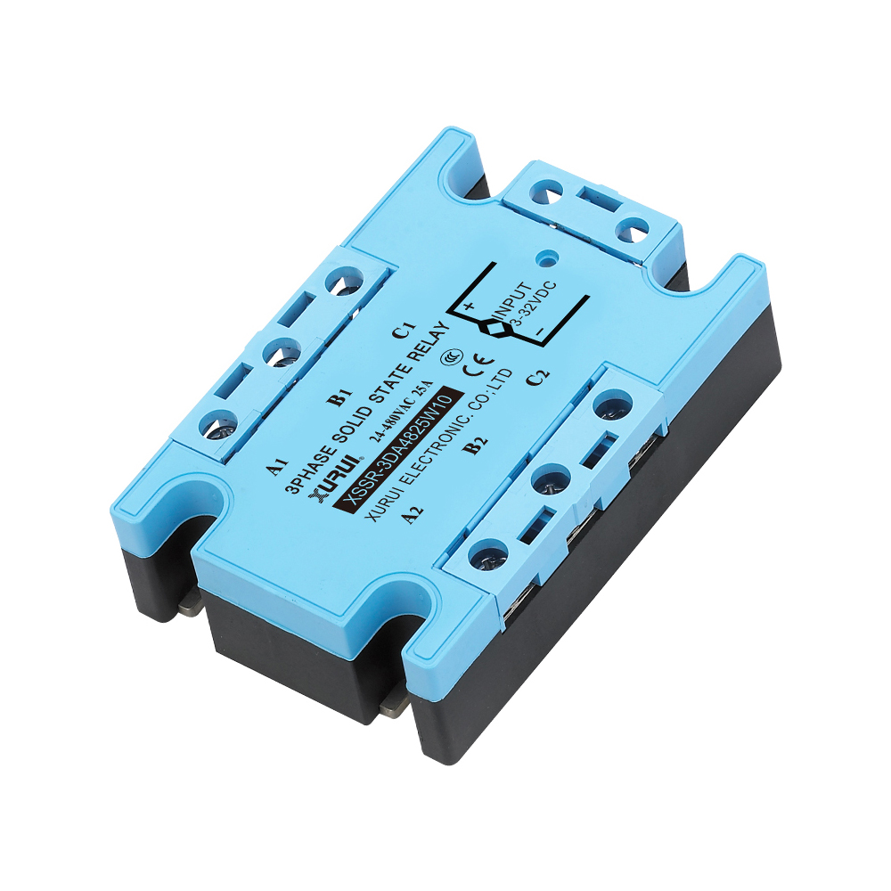
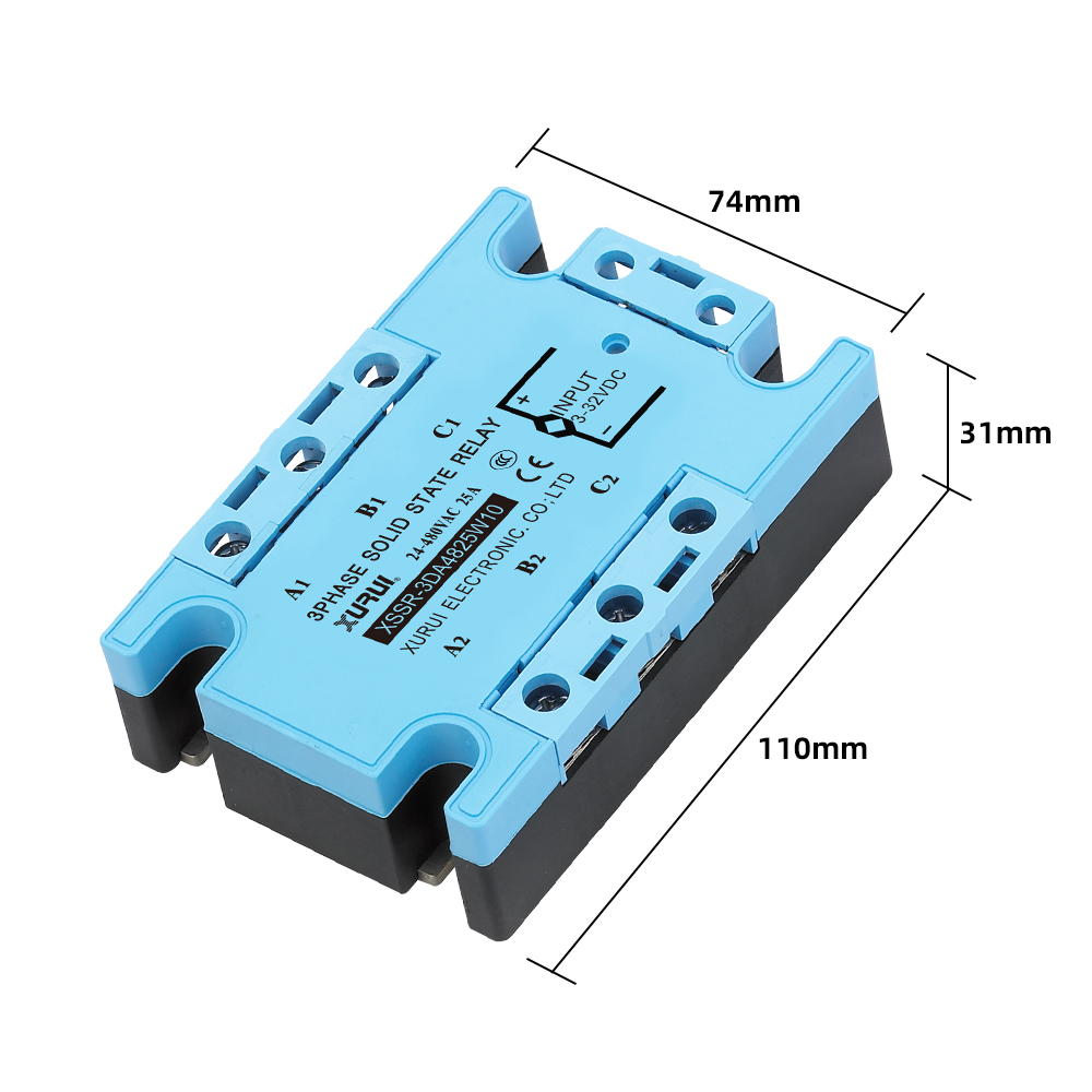
XSSR-W10 Three-Phase AC Solid State Relay

The XSSR-W10 is a compact and reliable three-phase AC solid state relay designed for industrial power control and automation applications. Featuring opto-electronic isolation, built-in RC snubber protection, and LED status indication, it provides stable switching performance for three-phase AC loads. Available with either DC or AC control input options, the XSSR-W10 supports load currents from 10A to 120A and offers both zero-crossing and random turn-on versions to accommodate different load requirements. Its compact bolt-mount housing makes installation simple while ensuring long-term operational reliability.

Control Voltage: 3–32VDC / 80–250VAC

Load Voltage: 24–480VAC

Rated Load Current: 10A–120A

2e68a3da4c690a02.webp

Product Features
  • Maintenance-Free Operation
    Maintenance-Free Operation

    Solid-state construction eliminates mechanical contacts, ensuring long service life and silent operation.

  • Compact Bolt-Mount Design
    Compact Bolt-Mount Design

    Space-saving housing design enables convenient installation while maintaining excellent mechanical strength.

  • LED Status Indicator
    LED Status Indicator

    Built-in LED indicator provides clear visual confirmation of relay operation.

  • Built-In RC Snubber Circuit
    Built-In RC Snubber Circuit

    Integrated surge suppression circuit helps protect the relay from voltage transients and improves reliability.

  • Zero-Crossing or Random Triggering
    Zero-Crossing or Random Triggering

    Available in zero-crossing and random-fire versions to match different application requirements.

  • Thyristor Output Structure
    Thyristor Output Structure

    Uses bidirectional thyristor or anti-parallel thyristor technology for reliable AC load switching performance.

  • Opto-Electronic Isolation
    Opto-Electronic Isolation

    Provides electrical isolation between control and load circuits, enhancing system safety and noise immunity.

  • Wide Current Range
    Wide Current Range

    Supports load currents from 10A to 120A, suitable for heaters, industrial machinery, motors, and automation equipment.

  • Flexible Control Input
    Flexible Control Input

    Available with DC input (3–32VDC) or AC input (80–250VAC) to support a wide variety of control circuits.

  • Three-Phase AC Switching
    Three-Phase AC Switching

    Designed for efficient switching and control of three-phase AC loads in industrial automation and power control systems.
Specifications
Product modelXSSR-3DA48□W10XSSR-3AA48□W10
Control voltage3-32VDC80-250VAC
Control current10-30mA10-30mA
Reverse voltage32VDC/
Guarantee close voltage1VDC30VAC
Guarantee open voltage3VDC80VAC
Load voltage24-480VAC
Load max current10A-120A
Load mini current0.08A
Breakover voltage≤1.8VAC
Output leakage current≤8mA
Medium withstand voltage≥2500VAC
Insulating resistance≥100MΩ
Switching time≤10mS
Frequency range50-60Hz
Operating temperature-20-70℃
load current safety factorResistive load 50-60%
Inductive load 30-40%
Product Certification
  • 01Certification for the Chinese market

    Compliant with GB national standards, with CCC and CQC certification for domestic sales and bidding compliance.

    Certification for the Chinese market Certification for the Chinese market
  • 02EU Market Certification

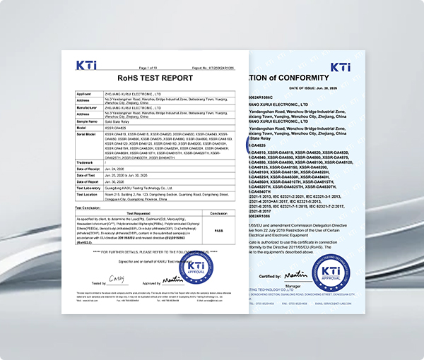
    Comply with CE, RoHS, REACH and EN standards, approved by TÜV & VDE, and support ATEX certification for explosive hazardous areas.

    EU Market Certification EU Market Certification EU Market Certification
  • 03North American Market Certification

    UL, CUL and CSA certified, conforming to North American electrical safety specifications for US and Canada market access.

    North American Market Certification
  • 04Japanese, Korean, and Asian markets

    Adapt to Japanese PSE and Korean KC certification, follow JIS and KS local standards to meet market access regulations of Japan and South Korea.

    Japanese, Korean, and Asian markets
Product Introduction & Process
  • 1
    Electronic Component Inspection

    Optocouplers, thyristors, triacs, MOSFETs, IGBTs, diodes, resistors, capacitors, varistors, LEDs, transformers, terminal blocks, ceramic substrates, PCBs, and aluminum heat sinks are inspected before production. Electrical parameters and supplier batch information are verified.

    2
    Power Device Selection and Matching

    Power semiconductor devices are screened according to blocking voltage, trigger characteristics, leakage current, on-state voltage, current capacity, and thermal performance. Components are matched according to the required relay voltage and current rating.

    3
    PCB or Power Substrate Preparation

    Printed circuit boards, ceramic substrates, or metal-based power substrates are cleaned and inspected. Solder pads, conductive tracks, insulation distances, and mounting surfaces are checked before electronic assembly.

    4
    SMT Component Placement

    Solder paste is accurately printed onto the PCB. Surface-mount components are positioned by automated placement equipment and soldered through a controlled reflow process. Temperature profiles are monitored to prevent insufficient soldering or thermal damage.

    5
    Through-Hole Component Assembly

    Power semiconductors, optocouplers, terminal blocks, transformers, LEDs, and other through-hole components are inserted according to the circuit design. Components are wave-soldered or manually soldered using controlled temperature and soldering time.

    6
    Solder Joint Inspection

    Solder joints are inspected visually or through automated optical inspection. The inspection checks for insufficient solder, bridging, cold joints, component misalignment, polarity errors, and contamination.

    7
    Circuit Cleaning and Preliminary Testing

    Flux residue and contaminants are removed where required. The assembled circuit is tested for input response, output switching, polarity, LED indication, short circuits, and basic insulation performance before encapsulation.

    8
    Heat Dissipation Assembly

    Power devices are mounted onto aluminum heat sinks, metal bases, or thermally conductive housings. Thermal grease, insulation pads, ceramic sheets, and controlled fastening torque are used to achieve reliable heat transfer while maintaining electrical isolation.

    9
    Protection Circuit Installation

    Depending on the model, RC snubber circuits, MOV surge protectors, transient suppression devices, over-temperature protection, or monitoring circuits are installed and verified.

    10
    Potting and Encapsulation

    The electronic assembly is positioned inside the housing and filled with insulating epoxy or thermally conductive encapsulating material. Vacuum treatment may be used to reduce trapped air. The resin is cured under controlled temperature and time conditions.

    11
    Electrical Performance Testing

    Each relay is tested for input trigger voltage, release voltage, input current, output leakage current, on-state voltage drop, zero-crossing characteristics, random-trigger response, insulation resistance, and dielectric strength.

    12
    Load and Thermal Testing

    The relay is operated under a specified load to verify switching stability and heat dissipation. Case temperature, semiconductor temperature rise, terminal temperature, and output waveform are monitored during testing.

    13
    Burn-In and Reliability Screening

    Selected models or production batches undergo continuous powered operation, repeated switching, high-temperature aging, or thermal cycling. Unstable components and early-life failures are identified before shipment.

    14
    Final Inspection and Packaging

    Terminal torque, housing condition, labels, current ratings, control voltage markings, wiring identification, and mounting accessories are checked. Approved products receive batch codes and are packed with appropriate electrostatic and mechanical protection.

Download
  • All
  • Selection Guide
  • Product Manual
  • Outline Drawing
Application Scenarios
Customization & Delivery
We support the following types of customization
  • Electrical Parameter Customization :

    Custom voltage & current, AC/DC type, zero-cross or random trigger.

  • Mounting Structure Customization :

    Custom mounting, terminals and non-standard dimensions.

  • Heat Dissipation & Protection Customization :

    Custom heat dissipation, high isolation, potting and anti-corrosion protection.

  • Function Upgrade Customization :

    Overheat/overcurrent protection, anti-interference, delay and soft start optional.

  • Appearance & Brand Customization

    Custom logo, marking, OEM/ODM and personalized solution design.

  • Proofing Cycle

    Regular customization: 3-7 working days

    Complex Customization: 7-15 working days

    Urgent Sampling: 24-72 hours

  • Proofing Cost ( $ )

    2222 US dollars

  • MOQ

    Conventional products have no minimum order quantity. Customized products can be consulted with customer service

  • Delivery Time

    The delivery time usually varies depending on the quantity and model of the order, usually 3-5 days. For specific times, please consult us

Frequently Asked Questions
  • How can I get an accurate quotation?
  • What is not covered by the warranty?
  • What does the product warranty cover?
  • What is your standard production lead time?
  • Which certifications and compliance documents are available?
  • Can you support samples and small trial orders?
  • What customization services do you offer?
  • How long does custom sample development take?
  • How are custom sample costs calculated?
  • How do you ensure product traceability?
  • What quality inspections are performed?
Related Recommendations